|
iSensor-SPI-Buffer
1.15
Firmware for the iSensor-SPI-Buffer board to enable full throughput buffered data capture on Analog Devices IMUs
|
|
iSensor-SPI-Buffer
1.15
Firmware for the iSensor-SPI-Buffer board to enable full throughput buffered data capture on Analog Devices IMUs
|
iSensor-SPI-Buffer user (slave) SPI module More...
Functions | |
| void | User_SPI_Reset (bool register_mode) |
| Reset user SPI port. More... | |
| void | User_SPI_Burst_Setup () |
| Configures SPI for a burst buffer read. More... | |
| void | User_SPI_Burst_Disable () |
| Restore SPI functionality after a burst read. More... | |
| void | User_SPI_Update_Config (uint32_t CheckUnlock) |
| Updates the slave SPI (SPI2) config based on the USER_SPI_CONFIG register. More... | |
Variables | |
| volatile uint32_t | g_userburstRunning = 0u |
| volatile uint32_t | g_user_burst_start = 0u |
| static uint32_t | SPI2_CR1 |
| static uint32_t | SPI2_CR2 |
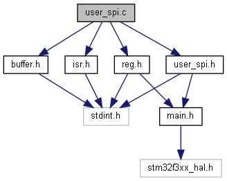
iSensor-SPI-Buffer user (slave) SPI module
Copyright (c) Analog Devices Inc, 2020 All Rights Reserved.
| void User_SPI_Burst_Disable | ( | ) |
Restore SPI functionality after a burst read.
This function disables SPI2 DMA requests via hard reset, and disables SPI2 DMA channel. It then re-configures the SPI for user mode.


| void User_SPI_Burst_Setup | ( | ) |
Configures SPI for a burst buffer read.
This function must be called when there is buffered data available to be read, which has been copied to the buffer output data registers.

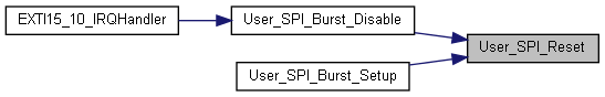
| void User_SPI_Reset | ( | bool | register_mode | ) |
Reset user SPI port.
Disable and re-enable SPI using RCC. Kind of hacky, not a clean way to do this. This is required because there is no way to clear Tx FIFO in the SPI peripheral otherwise when operating as a SPI slave.
After using the RCC to reset the SPI, it is configured for register mode (8-bit words, Rx interrupt on FIFO half full) or burst mode (16-bit mode, no interrupts).
| void User_SPI_Update_Config | ( | uint32_t | CheckUnlock | ) |
Updates the slave SPI (SPI2) config based on the USER_SPI_CONFIG register.
| CheckUnlock | Flag to check if the USER_SPI is unlocked (0xA5 written to config reg upper) |
This function performs all needed initialization for the slave SPI port, and should be called as start of the firmware start up process. If CheckUnlock is true, then the function will check that the upper 8 bits of USER_SPI_CONFIG is 0xA5. If it is not, the SPI update will not be processed. This prevents accidental writes to the SPI config register.
IMPORTANT! From the STM32F303 TRM:
When the data frame size fits into one byte (less than or equal to 8 bits), data packing is used automatically when any read or write 16-bit access is performed on the SPIx_DR register.
As such, words must be received byte-wise and transmitted word-wise (16-bit).

| volatile uint32_t g_user_burst_start = 0u |
Track if a user burst read has been started
| volatile uint32_t g_userburstRunning = 0u |
Track if a burst read is enabled. Global scope