|
iSensor-SPI-Buffer
1.15
Firmware for the iSensor-SPI-Buffer board to enable full throughput buffered data capture on Analog Devices IMUs
|
|
iSensor-SPI-Buffer
1.15
Firmware for the iSensor-SPI-Buffer board to enable full throughput buffered data capture on Analog Devices IMUs
|
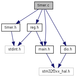
Implementation for for iSensor-SPI-Buffer timer module. Covers microsecond timer and PPS timer. More...
Functions | |
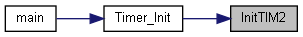
| static void | InitTIM2 (uint32_t timerfreq) |
| Enables IMU sample timestamp timer. More... | |
| static void | InitTIM8 () |
| Enables TIM8 as general 1MHz timer. | |
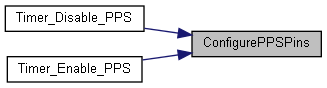
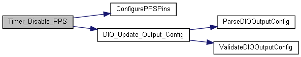
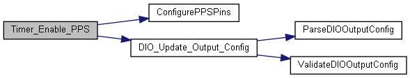
| static void | ConfigurePPSPins (uint32_t enable) |
| Configure PPS timer based on DIO_INPUT_CONFIG value. More... | |
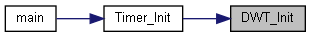
| static void | DWT_Init () |
| Init DWT peripheral. More... | |
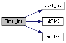
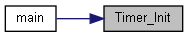
| void | Timer_Init () |
| Initialize all timers for operation. More... | |
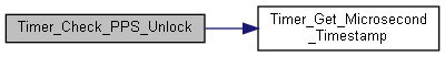
| void | Timer_Check_PPS_Unlock () |
| Check if the PPS signal is unlocked (greater than 1100ms since last PPS strobe) More... | |
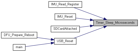
| void | Timer_Sleep_Microseconds (uint32_t microseconds) |
| Blocking sleep function call. More... | |
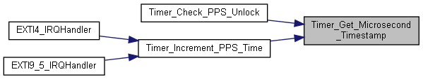
| uint32_t | Timer_Get_Microsecond_Timestamp () |
| Gets the current 32-bit value from the IMU sample timestamp timer. More... | |
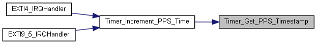
| uint32_t | Timer_Get_PPS_Timestamp () |
| Gets the current 32-bit value from PPS timestamp registers. More... | |
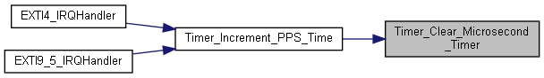
| void | Timer_Clear_Microsecond_Timer () |
| Reset TIM2 counter to 0. More... | |
| void | Timer_Enable_PPS () |
| Enable PPS input for time stamp synchronization (improved long term stability over 20ppm crystal). More... | |
| void | Timer_Disable_PPS () |
| Disable PPS timer functionality. More... | |
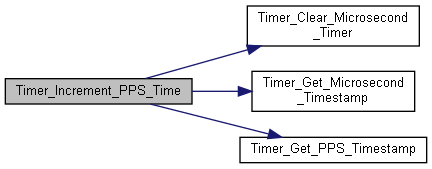
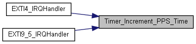
| void | Timer_Increment_PPS_Time () |
| Increment PPS timestamp by 1. More... | |
Variables | |
| uint32_t | g_PPSInterruptMask = 0 |
| static TIM_HandleTypeDef | htim2 |
| static TIM_HandleTypeDef | htim8 |
| static uint32_t | PPS_TickCount |
| static uint32_t | PPS_MaxTickCount |
Implementation for for iSensor-SPI-Buffer timer module. Covers microsecond timer and PPS timer.
Copyright (c) Analog Devices Inc, 2020 All Rights Reserved.
|
static |
Configure PPS timer based on DIO_INPUT_CONFIG value.
| enable | Bool flagging if PPS functionality is being enabled or disabled |
This function sets up the PPS input pin, as well as the expected "PPS" period.
|
static |
Init DWT peripheral.
This peripheral is used to count microseconds for the timer module.
|
static |
Enables IMU sample timestamp timer.
| timerfreq | The desired timer freq (in Hz) |
This function should be called as part of the buffered data acquisition startup process. The enabled timer is TIM2 (32 bit)
| void Timer_Check_PPS_Unlock | ( | ) |
Check if the PPS signal is unlocked (greater than 1100ms since last PPS strobe)
This function should be periodically called as part of the firmware housekeeping process
| void Timer_Clear_Microsecond_Timer | ( | ) |
Reset TIM2 counter to 0.
| void Timer_Disable_PPS | ( | ) |
Disable PPS timer functionality.
| void Timer_Enable_PPS | ( | ) |
Enable PPS input for time stamp synchronization (improved long term stability over 20ppm crystal).
The PPS input can be on any of the DIOx_Slave pins (host processor the iSensor-SPI-Buffer). The selected pin is configured by the PPS_SELECT field in the DIO_INPUT_CONFIG register. The trigger polarity for the PPS signal is configured by the PPS_POLARITY field in the DIO_INPUT_CONFIG register.
Pins:
DIO1: PB4 -> EXTI4 interrupt DIO2: PB8 -> EXTI9_5 interrupt, mask (1 << 8) DIO3: PC7 -> EXTI9_5 interrupt, mask (1 << 7) DIO4: PA8 -> EXTI9_5 interrupt, mask (1 << 8)
| uint32_t Timer_Get_Microsecond_Timestamp | ( | ) |
Gets the current 32-bit value from the IMU sample timestamp timer.
| uint32_t Timer_Get_PPS_Timestamp | ( | ) |
Gets the current 32-bit value from PPS timestamp registers.
| void Timer_Increment_PPS_Time | ( | ) |
Increment PPS timestamp by 1.
This function should be called whenever a PPS interrupt is generated. It handles PPS tick count incrementation, and resetting the microsecond timestamp every time one second has elapsed.
| void Timer_Init | ( | ) |
Initialize all timers for operation.
Timer 2 is used as a 1MHz timer for the timestamp measurements Timer 8 is used as a timeout timer, also at 1MHz
The DWT timer is used for a polling based timer
| void Timer_Sleep_Microseconds | ( | uint32_t | microseconds | ) |
Blocking sleep function call.
| microseconds | The number of microseconds to sleep |
This function uses TIM6 to perform delay.
| uint32_t g_PPSInterruptMask = 0 |
PPS interrupt source. Global scope
|
static |
TIM2 handle
|
static |
TIM8 handle for init
|
static |
Number of PPS ticks per sec
|
static |
Track number of "PPS" ticks which have occurred in last second