|
iSensor-SPI-Buffer
1.15
Firmware for the iSensor-SPI-Buffer board to enable full throughput buffered data capture on Analog Devices IMUs
|
|
iSensor-SPI-Buffer
1.15
Firmware for the iSensor-SPI-Buffer board to enable full throughput buffered data capture on Analog Devices IMUs
|
iSensor-SPI-Buffer main. Contains STM init functions and application cyclic executive. More...
#include "usb.h"#include "main.h"#include "reg.h"#include "imu.h"#include "usbd_cdc_if.h"#include "usb_device.h"#include "sd_card.h"#include "buffer.h"#include "user_interrupt.h"#include "flash.h"#include "led.h"#include "watchdog.h"#include "timer.h"#include "dio.h"#include "adc.h"#include "dfu.h"#include "user_spi.h"#include "data_capture.h"#include "script.h"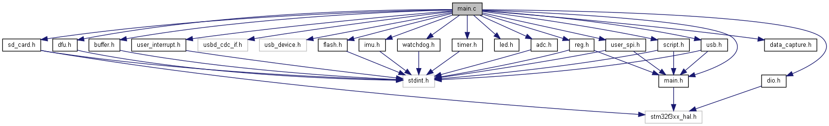
Functions | |
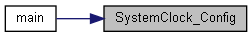
| static void | SystemClock_Config () |
| System Clock Configuration. More... | |
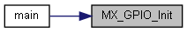
| static void | MX_GPIO_Init () |
| GPIO Initialization Function. More... | |
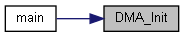
| static void | DMA_Init () |
| Init all DMA channels in use and configure DMA interrupts. More... | |
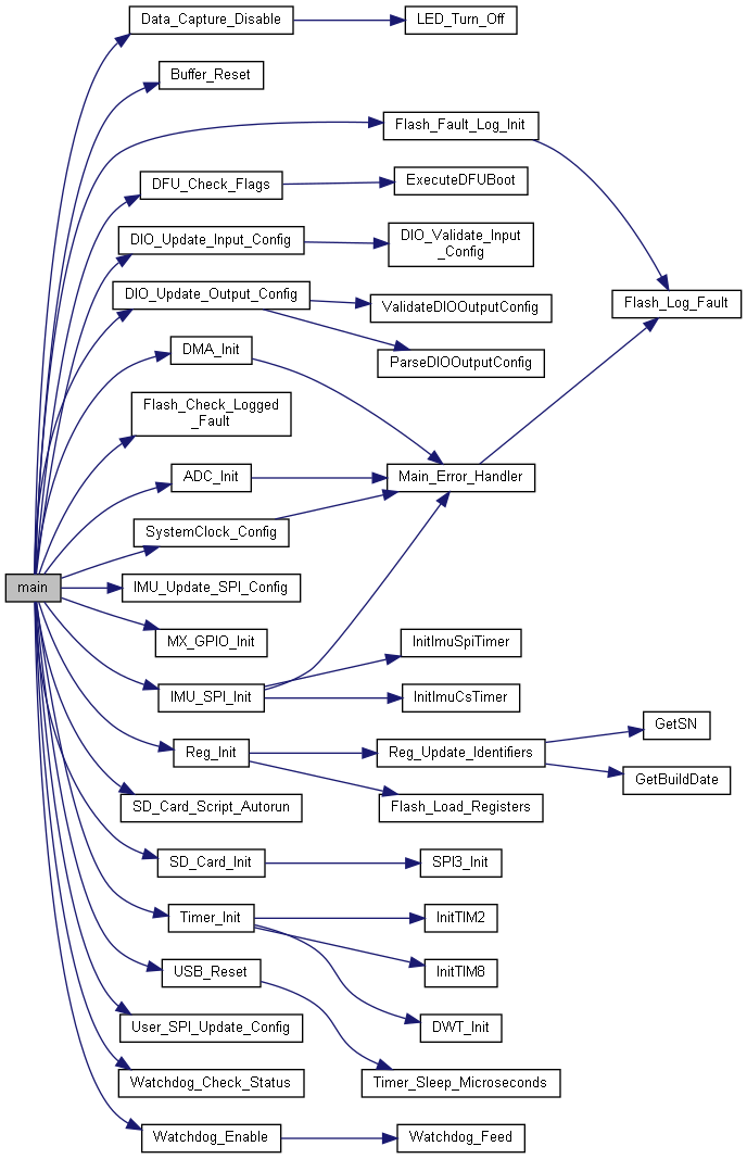
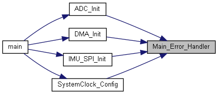
| int | main () |
| The application entry point. More... | |
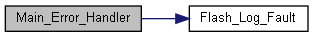
| void | Main_Error_Handler () |
| This function is executed in case of error occurrence. More... | |
Variables | |
| DMA_HandleTypeDef | g_dma_spi1_rx |
| DMA_HandleTypeDef | g_dma_spi1_tx |
| DMA_HandleTypeDef | g_dma_spi2_tx |
| SPI_HandleTypeDef | g_spi1 |
| SPI_HandleTypeDef | g_spi2 |
| static uint32_t | state |
iSensor-SPI-Buffer main. Contains STM init functions and application cyclic executive.
Copyright (c) Analog Devices Inc, 2020 All Rights Reserved.
|
static |
Init all DMA channels in use and configure DMA interrupts.
Currently use three DMA channels, on DMA peripheral 1: DMA2/3 - IMU SPI port, used for burst reads from IMU DMA5 - User SPI port, Used for buffer burst outputs. Rx not used
All DMA channels are configured to generate interrupts upon the completion of a transfer. The user SPI DMA interrupt is used just to check for any error events which might have occurred during the burst read process.
The IMU DMA interrupts are used to determine when a burst read from the IMU has completed. Both the Tx and Rx channels must be done for a burst read to have completed (Tx should finish last).

| int main | ( | ) |
The application entry point.
| void Main_Error_Handler | ( | ) |
This function is executed in case of error occurrence.
During init, errors are logged, then init continues. This is done to reduce potential for a fault locking the device in a reset loop.
|
static |
GPIO Initialization Function.
TIM3 GPIO Configuration PA4 ---—> TIM3_CH2
|
static |
System Clock Configuration.
Initializes the CPU, AHB and APB busses clocks
Initializes the CPU, AHB and APB busses clocks

| DMA_HandleTypeDef g_dma_spi1_rx |
IMU SPI Rx DMA handle. Global scope
| DMA_HandleTypeDef g_dma_spi1_tx |
IMU SPI Tx DMA handle. Global scope
| DMA_HandleTypeDef g_dma_spi2_tx |
User SPI Tx DMA handle. Global scope
| SPI_HandleTypeDef g_spi1 |
SPI handle for IMU master port. Global scope
| SPI_HandleTypeDef g_spi2 |
SPI handle for slave port (from master controller). Global scope
|
static |
Track the cyclic executive state