|
iSensor-SPI-Buffer
1.15
Firmware for the iSensor-SPI-Buffer board to enable full throughput buffered data capture on Analog Devices IMUs
|
|
iSensor-SPI-Buffer
1.15
Firmware for the iSensor-SPI-Buffer board to enable full throughput buffered data capture on Analog Devices IMUs
|
iSensor-SPI-Buffer interrupt service routines More...
#include "reg.h"#include "imu.h"#include "isr.h"#include "buffer.h"#include "user_spi.h"#include "dio.h"#include "flash.h"#include "main.h"#include "data_capture.h"#include "timer.h"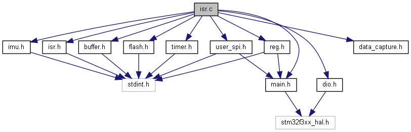
Functions | |
| static void | FinishImuBurst () |
| Cleans up an IMU burst data read. More... | |
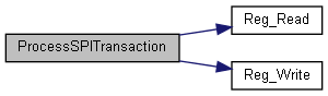
| static void | ProcessSPITransaction (uint32_t rx) |
| Process a 16 bit data word from the user SPI. More... | |
| void | EXTI9_5_IRQHandler () |
| IMU data ready ISR. Kicks off data capture process. More... | |
| void | EXTI4_IRQHandler () |
| EXTI 4 interrupt handler. More... | |
| void | TIM4_IRQHandler () |
| IMU SPI timer ISR. More... | |
| void | DMA1_Channel2_IRQHandler (void) |
| This function handles DMA1 channel2 global interrupt (spi1 (IMU) Rx). More... | |
| void | DMA1_Channel3_IRQHandler (void) |
| This function handles DMA1 channel3 global interrupt (spi1 (IMU) Tx). More... | |
| void | DMA1_Channel5_IRQHandler (void) |
| This function handles DMA1 channel5 global interrupt (spi2 (user) Tx). More... | |
| void | SPI2_IRQHandler (void) |
| This function handles the user SPI (SPI2) rx data interrupt. More... | |
| void | EXTI15_10_IRQHandler (void) |
| This function handles the user SPI (SPI2) chip select rising edge. More... | |
| void | HardFault_Handler (void) |
| This function handles Hard fault interrupt. More... | |
| void | MemManage_Handler (void) |
| This function handles Memory management fault. More... | |
| void | BusFault_Handler (void) |
| This function handles Pre-fetch fault, memory access fault. More... | |
| void | UsageFault_Handler (void) |
| This function handles Undefined instruction or illegal state. More... | |
Variables | |
| volatile uint32_t | g_wordsPerCapture |
| volatile uint32_t | g_captureInProgress = 0u |
| static uint8_t * | BufferElementHandle |
| static uint16_t * | BufferSigHandle |
| static volatile uint32_t | WordsCaptured |
| static uint32_t | BufferSignature |
| static volatile uint32_t | ImuDMADone = 0 |
iSensor-SPI-Buffer interrupt service routines
Copyright (c) Analog Devices Inc, 2020 All Rights Reserved.
| void BusFault_Handler | ( | void | ) |
This function handles Pre-fetch fault, memory access fault.

| void DMA1_Channel2_IRQHandler | ( | void | ) |
This function handles DMA1 channel2 global interrupt (spi1 (IMU) Rx).
This DMA is used to receive data from an IMU during a burst data capture. In order for an IMU data capture to be complete, this DMA channel and the transmit DMA channel have to both finish their work. In general, this channel will finish last.
| void DMA1_Channel3_IRQHandler | ( | void | ) |
This function handles DMA1 channel3 global interrupt (spi1 (IMU) Tx).
This DMA is used to transmit the write data array to the IMU during a burst data capture. It runs in parallel with DMA channel 2 to achieve full duplex burst.
| void DMA1_Channel5_IRQHandler | ( | void | ) |
This function handles DMA1 channel5 global interrupt (spi2 (user) Tx).
This interrupt is only used to flag errors. Ending a buffer burst output is triggered by an EXTI interrupt attached to chip select.
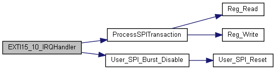
| void EXTI15_10_IRQHandler | ( | void | ) |
This function handles the user SPI (SPI2) chip select rising edge.
Two interrupts are used for the user SPI interface. In register mode, the SPI2 interrupt is used to interrupt when two bytes are received, to avoid an unnecessary dependency on the CS state (caused issues for some Linux systems which like to toggle CS after each byte). This interrupt is used when in burst mode only. In burst mode, a variable number of bytes is clocked out, so the CS rising edge must be used to delimit the end of a transaction.
In this interrupt, if another burst read is requested, the CS rising edge interrupt is kept enabled, and the buffer board is configured for another burst. If a standard register read/write is requested, then the CS interrupt is disabled, and the standard SPI interrupt re-enabled.
When this function is called, the SPI should be operating in 16-bit mode, rather than the 8-bit mode used for register interfacing.
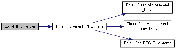
| void EXTI4_IRQHandler | ( | ) |
EXTI 4 interrupt handler.
This interrupt is generated by a PPS signal applied to DIO1 only. All other PPS inputs generate an EXTI9_5 interrupt
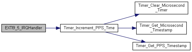
| void EXTI9_5_IRQHandler | ( | ) |
IMU data ready ISR. Kicks off data capture process.
All four DIOx_Master pins map to this interrupt handler. Only one should be enabled as an interrupt source at a time. This interrupt also handles PPS input signals for DIO2-4. The EXTI pending interrupt register (PR) can be used to identify if the interrupt is coming from a PPS strobe or an IMU data ready signal.
|
static |
Cleans up an IMU burst data read.
This function is called once the SPI1 Tx and Rx DMA interrupts have both fired, or a single error interrupt has been generated. SPI1 uses DMA1, channel 2/3. These channels have lower priority than the user SPI DMA channels, which also use DMA peripheral 1.
This function brings CS high, calculates the buffer signature, and updates the buffer count / capture state variables. Before this function is called, DMA interrupts should be disabled (by their respective ISR's)
| void HardFault_Handler | ( | void | ) |
This function handles Hard fault interrupt.

| void MemManage_Handler | ( | void | ) |
This function handles Memory management fault.

|
static |
Process a 16 bit data word from the user SPI.
| rx | Two bytes from the user SPI in register mode, packed |
This function accommodates for the swapped endianess of bytes which are packed into the SPI Rx data register.
If the value on the SPI bus is: 0x1234, then the data register will hold 0x3412. This is true for both receive and transmit.
IMPORTANT: This should only be used for register mode, when the SPI data word size is 8 bits. In burst mode, where the SPI data word size is 16 bits, this will not work, since data packing is not used.

| void SPI2_IRQHandler | ( | void | ) |
This function handles the user SPI (SPI2) rx data interrupt.
The SPI Rx data interrupt is used for standard register reads. The SPI2 peripheral is configured to generate an interrupt once two bytes of data have been received.
IMPORTANT NOTE: Due to data packing, each read from the SPI data register actually pulls two bytes from the Rx FIFO. These bytes are in reversed order from how they were received on the bus. For more information on this behavior, see the data packing section of the SPI entry in the technical reference manual.
If a burst read is requested, this interrupt is disabled, and the CS rising edge interrupt is enabled instead. This allows for variable length burst read transactions. The hand off from register mode to burst mode and back requires special care. We want to avoid potential issues if the user just immediately starts full length burst reads, rather than requesting a burst first. We essentially have to wait for the current SPI transaction to finish before enabling the burst. Otherwise, the burst can potentially get enabled half way through this transfer, which messes up the whole burst read sequence. We could accomplish this by polling CS in the ISR, but that has a strong potential to mess with other functionality (user SPI interrupt is highest priority, and also generally polling in an ISR is a bad idea). Instead, a flag is set, which must be cleared by the CS ISR. This flag is checked by the buffer dequeue routine which runs from the main loop.
Once no more bursts are requested, the SPI2 interrupt will be re-enabled through the user SPI burst disable function.

| void TIM4_IRQHandler | ( | ) |
IMU SPI timer ISR.
This interrupt retrieves the SPI data read on the previous SPI transaction. It then starts the next SPI transaction (if needed) and returns.
SPI MISO data
| void UsageFault_Handler | ( | void | ) |
This function handles Undefined instruction or illegal state.

|
static |
Pointer to buffer element which is being populated
|
static |
Pointer to buffer data signature within buffer element which is being populated
|
static |
Buffer signature
| volatile uint32_t g_captureInProgress = 0u |
Track if there is currently a capture in progress
| volatile uint32_t g_wordsPerCapture |
Current capture size (in 16 bit words). Global scope
|
static |
Flag to track if IMU burst DMA is done
|
static |
Track number of words captured within current buffer entry