Implementation for iSensor-SPI-Buffer IMU interfacing module.
More...
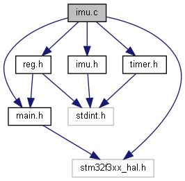
#include "reg.h"
#include "imu.h"
#include "main.h"
#include "timer.h"
#include "stm32f3xx_hal.h"
Implementation for iSensor-SPI-Buffer IMU interfacing module.
Copyright (c) Analog Devices Inc, 2020 All Rights Reserved.
- Date
- 3/18/2020
- Author
- A. Nolan (alex..nosp@m.nola.nosp@m.n@ana.nosp@m.log..nosp@m.com)
◆ ApplySclkDivider()
| static void ApplySclkDivider |
( |
uint32_t |
preScalerSetting | ) |
|
|
static |
Applies baud rate divider setting to master SPI port (to IMU)
- Parameters
-
| preScalerSetting | The SCLK pre-scaler setting to apply. |
- Returns
- void
◆ ConfigureImuCsTimer()
| static void ConfigureImuCsTimer |
( |
uint32_t |
period | ) |
|
|
static |
Sets the TIM3 period for use in PWM mode to drive CS.
- Returns
- void
- Parameters
-
| period | Timer ticks period for TIM3. This corresponds to the CS low pulse width |
TIM3 will be disabled (CS high) by this function. It should not be called while a data capture is in progress. This function must be called whenever the IMU SPI interface settings are updated, either at startup or on demand by the user.
◆ ConfigureImuSpiTimer()
| static void ConfigureImuSpiTimer |
( |
uint32_t |
period | ) |
|
|
static |
Configures the period on TIM4.
- Parameters
-
| period | The timer period (in 72MHz ticks) |
- Returns
- void
This function must be called whenever the IMU SPI interface settings are updated, either at startup or on demand by the user.
◆ IMU_Disable_SPI_DMA()
| void IMU_Disable_SPI_DMA |
( |
| ) |
|
Disable IMU burst data stream.
- Returns
- void
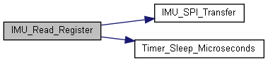
◆ IMU_Read_Register()
| uint16_t IMU_Read_Register |
( |
uint8_t |
RegAddr | ) |
|
Reads 16 bit value from the IMU.
- Parameters
-
| RegAddr | The IMU register address to read |
- Returns
- The 16 bit register data read from the IMU
This function produces two SPI transfers to the IMU. One to send the initial read request, and a second to get back the read result data.
A stall time is inserted between the two words, as well as after the last word. This is needed when accessing the IMU over USB - don't want to read requests to be immediately back to back.
◆ IMU_Reset()
Hardware reset connected IMU.
- Returns
- void
Reset pin is pulled low for 1ms, then brought high
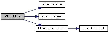
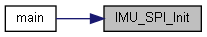
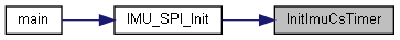
◆ IMU_SPI_Init()
SPI1 Initialization Function (master SPI port to IMU)
- Returns
- void
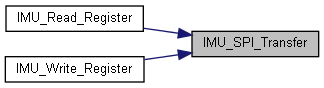
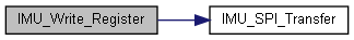
◆ IMU_SPI_Transfer()
| uint16_t IMU_SPI_Transfer |
( |
uint32_t |
MOSI | ) |
|
Basic IMU SPI data transfer function (protocol agnostic).
- Parameters
-
| MOSI | The 16 bit MOSI data to transmit to the IMU |
- Returns
- The 16 bit MISO data received during the transmission
This function wraps the SPI master HAL layer into something easily usable. All SPI pass through functionality is built on this call.
◆ IMU_Start_Burst()
| void IMU_Start_Burst |
( |
uint8_t * |
bufEntry | ) |
|
Start an IMU burst data capture (using DMA)
- Parameters
-
| bufEntry | Pointer to the buffer entry to recieve data into |
- Returns
- void
This function configures the IMU SPI port for a bi-directional DMA transfer. CS is manually controlled by leaving TIM3 (CS timer) disabled, and manually setting the count register to 0.
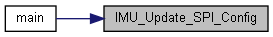
◆ IMU_Update_SPI_Config()
| void IMU_Update_SPI_Config |
( |
| ) |
|
Processes any changes to IMU_SPI_CONFIG reg and applies.
- Returns
- void
Sets the stall time (in microseconds) based on lower byte of the IMU_SPI_CONFIG register. Sets the SPI clock frequency divider based on the upper 8 bits. See register documentation for details of what target SCLK frequencies are achievable.
◆ IMU_Write_Register()
| uint16_t IMU_Write_Register |
( |
uint8_t |
RegAddr, |
|
|
uint8_t |
RegValue |
|
) |
| |
Writes an 8 bit value to the IMU.
- Parameters
-
| RegAddr | The IMU register address to write |
| RegValue | The 8 bit value to write |
- Returns
- The MISO data clocked out from the IMU during the transaction
This function produces only a single SPI transaction to the IMU
◆ InitImuCsTimer()
| static void InitImuCsTimer |
( |
| ) |
|
|
static |
Inits TIM3 for use in PWM mode to drive CS.
- Returns
- void
TIM4 is used to drive SPI buffered data acquisition from the IMU. One timer interrupt is generated per SPI word clocked out from the DUT. TIM4 runs at a full 72MHz. With a 16-bit resolution and a time base of 72MHz, TIM4 will roll over every 910us The worst case spi period allowed is 255us stall + (17 bits / 140KHz) -> 376us
◆ InitImuSpiTimer()
| static void InitImuSpiTimer |
( |
| ) |
|
|
static |
Inits TIM4 for use as a IMU spi period timer.
- Returns
- void
TIM4 is used to drive SPI buffered data acquisition from the IMU. One timer interrupt is generated per SPI word clocked out from the DUT. TIM4 runs at a full 72MHz. With a 16-bit resolution and a time base of 72MHz, TIM4 will roll over every 910us The worst case spi period allowed is 255us stall + (17 bits / 140KHz) -> 376us
◆ htim3
◆ htim4
◆ imuStallTimeUs
| uint32_t imuStallTimeUs = 25 |
|
static |
track stall time (microseconds)