|
iSensor-SPI-Buffer
1.15
Firmware for the iSensor-SPI-Buffer board to enable full throughput buffered data capture on Analog Devices IMUs
|
|
iSensor-SPI-Buffer
1.15
Firmware for the iSensor-SPI-Buffer board to enable full throughput buffered data capture on Analog Devices IMUs
|
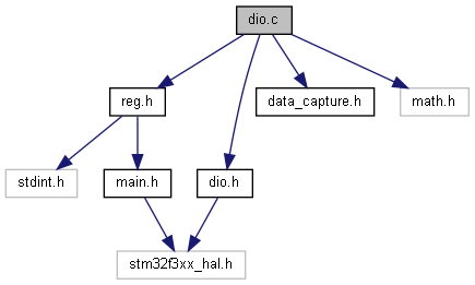
Implementation file for iSensor-SPI-Buffer DIO interfacing module. More...
Functions | |
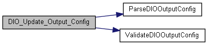
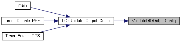
| static void | ValidateDIOOutputConfig () |
| validates the current DIO config struct settings More... | |
| static uint16_t | BuildDIOOutputConfigReg () |
| Parse local config struct to DIO_CONFIG reg value. More... | |
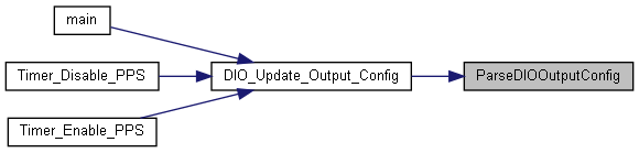
| static void | ParseDIOOutputConfig () |
| Parse DIO_CONFIG reg to local config struct. More... | |
| void | DIO_Start_Sync_Gen () |
| Generates a clock on DIO2_Slave based on frequency in SYNC_FREQ. More... | |
| uint32_t | DIO_Get_Hardware_ID () |
| Gets two bit hardware identification code from identifier pins. More... | |
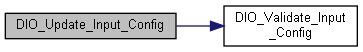
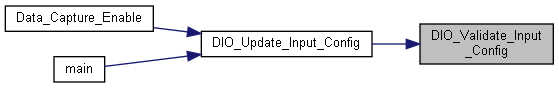
| void | DIO_Validate_Input_Config () |
| Validates the DIO_INPUT_CONFIG value. More... | |
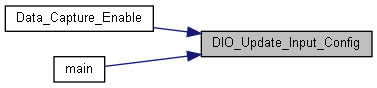
| void | DIO_Update_Input_Config () |
| Validates and updates the data ready input configuration based on DIO_INPUT_CONFIG. More... | |
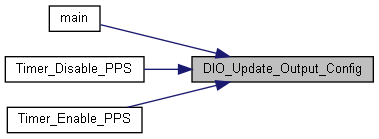
| void | DIO_Update_Output_Config () |
| Validates DIO_OUTPUT_CONFIG settings and applies to GPIO. More... | |
Variables | |
| volatile DIOConfig | g_pinConfig = {} |
| static TIM_HandleTypeDef | htim16 |
Implementation file for iSensor-SPI-Buffer DIO interfacing module.
Copyright (c) Analog Devices Inc, 2020 All Rights Reserved.
This module manages all interrupts (error, watermark) as well as configuring the pin passthrough and sync generation.
|
static |
Parse local config struct to DIO_CONFIG reg value.
| uint32_t DIO_Get_Hardware_ID | ( | ) |
Gets two bit hardware identification code from identifier pins.
| void DIO_Start_Sync_Gen | ( | ) |
Generates a clock on DIO2_Slave based on frequency in SYNC_FREQ.
This can be disabled by restoring DIO2_Slave to input/output mode through a write to DIO_OUTPUT_CONFIG.
The target freq can be in the range 1Hz - 65535Hz. This function adaptively sets the timer16 prescaler value to allow the most precise frequency.
The timer16 is clocked off the system clock of 72MHz. For a given target freq, the output freq can be calculated as:
72MHz / preScale
freq = --------------— period
Where period and preScale are limited to 16-bits. The total cycles can then be calculated as:
cycles = 72000000 / freq
This value may be more than 0xFFFF, so
preScale = (cycles / 0xFFFF) + 1
Then:
period = 72000000 / (preScale * freq)
TIM16 GPIO Configuration PB8
| void DIO_Update_Input_Config | ( | ) |
Validates and updates the data ready input configuration based on DIO_INPUT_CONFIG.
This function validates the DIO_INPUT_CONFIG contents, then uses the selected DR configuration to enable the selected DIOn_Master pin as an interrupt source with the desired polarity. This function does not enable PPS input (just ensures that only one bit is set).
| void DIO_Update_Output_Config | ( | ) |
Validates DIO_OUTPUT_CONFIG settings and applies to GPIO.
General procedure is as follows:
passPins Set SW_IN1 - SW_IN4 output values based on passPins. These act as inputs to the ADG1611 analog switch. For each bit set in passPins, configure the corresponding DIOx_Slave signal as an input (tristate). Only perform this configuration if the pin is not currently acting as a PPS input
watermarkPins Configure selected watermark interrupt pins as output GPIO
overflowPins Configure selected overflow interrupt pins as output GPIO
errorPins Configure selected error interrupt pins as output GPIO
Any pins which are unused will be configured as inputs.
| void DIO_Validate_Input_Config | ( | ) |
Validates the DIO_INPUT_CONFIG value.
This function clears any unused bits in DIO_INPUT_CONFIG and ensures that only one DIO pin is selected as data ready. If no data ready pin is selected, it defaults to DIO1.
|
static |
Parse DIO_CONFIG reg to local config struct.
|
static |
validates the current DIO config struct settings
| volatile DIOConfig g_pinConfig = {} |
Struct storing current DIO output config. Global scope
|
static |
TIM16 handle