|
iSensor-SPI-Buffer
1.15
Firmware for the iSensor-SPI-Buffer board to enable full throughput buffered data capture on Analog Devices IMUs
|
|
iSensor-SPI-Buffer
1.15
Firmware for the iSensor-SPI-Buffer board to enable full throughput buffered data capture on Analog Devices IMUs
|
Implementation file for iSensor-SPI-Buffer ADC module (for temp sensor and Vdd monitoring) More...
#include "reg.h"#include "adc.h"#include "main.h"#include "stm32f3xx_hal.h"#include "stm32f3xx_hal_conf.h"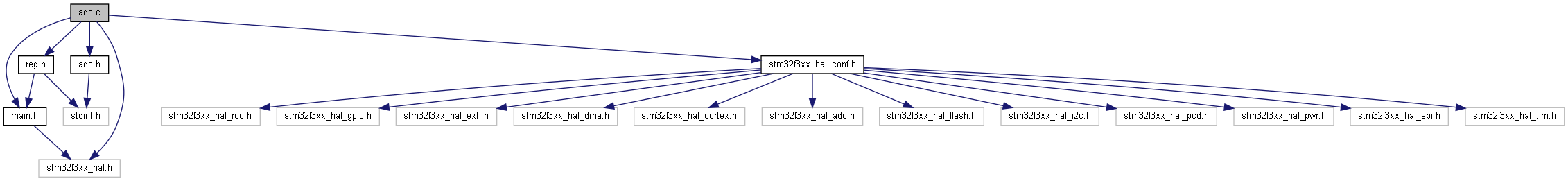
Functions | |
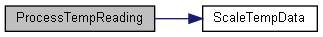
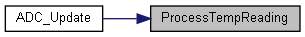
| static void | ProcessTempReading () |
| Handle end of conversion for a temp sensor value. More... | |
| static int16_t | ScaleTempData (uint32_t rawTemp) |
| Scale raw ADC temperature data to temp output. More... | |
| static uint16_t | GetVdd (uint32_t VrefMeasurement) |
| Calculate Vdd from VREFINT measurement. More... | |
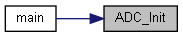
| void | ADC_Init () |
| ADC1 Initialization Function. More... | |
| void | ADC_Update () |
| Read and scale ADC values then load to output registers. More... | |
Variables | |
| static ADC_HandleTypeDef | hadc1 |
Implementation file for iSensor-SPI-Buffer ADC module (for temp sensor and Vdd monitoring)
Copyright (c) Analog Devices Inc, 2020 All Rights Reserved.
| void ADC_Init | ( | ) |
ADC1 Initialization Function.
This function should be called once as part of the firmware initialization process.
Initializes ADC1 in single sampling mode, with two input channels converted (temp sensor and VREFINT). The sample time is set to 601 ADC cycles. The ADC is clocked from 72MHz core clock divided by 8. 601 cycles / (72MHz/8) -> 66us. The Temp sensor requires a minimum 10us setting time for accurate measurements. Because these values are measured for diagnostics monitoring pursposes only, using a long sample time is not a problem.

| void ADC_Update | ( | ) |
Read and scale ADC values then load to output registers.
This function drives the ADC state machine and should be called periodically from the cyclic executive. The ADC is configured in non-continuous scanning mode, with the temp sensor and VREFINT channels enabled. For each channel, the state machine initiates an ADC sample, then goes to a wait state which does not advance until the EOC flag for that sample has been set. The VREFINT channel is sampled prior to the temp sensor channel, because the calculated Vdd value is used to compensate the temp sensor scale factor.

|
static |
Calculate Vdd from VREFINT measurement.
VREFINT as a regulated ~1.23V supply generated by the STM32 processor core internally. The value of VREFINT with Vdd = 3.3V is logged by ST during production (stored in VREFINT_CAL). Theoretical value of 1501
In general, when an ADC measurement is performed, the ADC output = (2^12 - 1) * voltage / Vdd
so Vref (real voltage) = VREFINT_CAL * 3.3 / (2^12 - 1)
Therefore a measurement of the current Vref is equivalent to:
VrefMeasurement = (2^12 - 1) * (VREFINT_CAL * 3.3 / (2^12 - 1)) / Vdd VrefMeasurement = VREFINT_CAL * 3.3 / Vdd Vdd = VREFINT_CAL * 3.3 / VrefMeasurement
|
static |
Handle end of conversion for a temp sensor value.
This function reads the latest temp sensor output value and applies it to the temp sensor decimation averaging filter. If the end of a decimation period has been reached, it updates the temperature sensor output value and flags any temperature over range events in the STATUS register (outside -40C to 85C).
|
static |
Scale raw ADC temperature data to temp output.
Temp (in C, 10LSB per degree) = (800 / (TS_CAL2 - TS_CAL1)) * (val - TS_CAL1) + 300
The CAL values are measured with VREF = 3.3V at the factory. To make the measurement accurate, the most recent value read for VDD (using ADC VREFINT measurement) is used to normalize the raw temperature sensor measurement to a 3.3V reference voltage.

|
static |
HAL ADC handle